ULTRASOUND MACHINES - “Knobology”
Use this page to understand our machines, probes, how to scan with our machines.
Know thy Machine!
Never:
Run over probe cords
Drop probes
Hang probes from non-designated holders
Always:
Clean the probes and keypad before and after each use
Put machines where they belong in the department
Plug in machines following use
The University Hospital ED currently employs 2 different machines
It is important to care for the machines and their components!
THE MACHINES

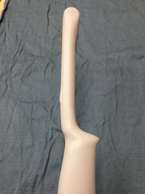
THE PROBES
These are the true workhorses of the ultrasound machine. Each probe contains piezoelectric crystals which vibrate under electric current. When these crystals vibrate, they produce sound that penetrates into tissues. The probe also acts as a receiver for returning echo, which in turn, cause vibration of the crystals that the probe converts to current, that is later interpreted as data by the ultrasound machine.
While there are many types of probes available for POC (point-of-care) ultrasound, there are 4 that are encountered most commonly.
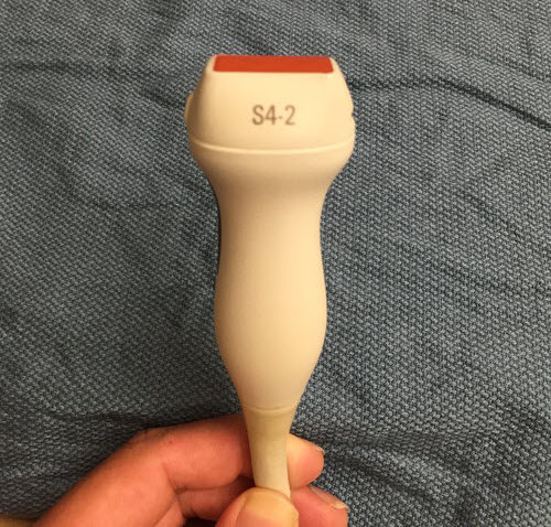
Phased array: often referred to as the ‘cardiac probe’ this is a low frequency (1-5MHz) probe which is scanning the abdomen, retroperitoneal and even soft tissue structures. Given the low frequency, you can expect this to have good penetration, at the expense of resolution. Not great for visualizing small superficial structures. The phased array probe also has a small footprint (area of probe surface) which makes it ideal for getting between the ribs in cardiac studies.
Curvilinear or Curved Array Probe: often referred to as the ‘abdominal probe’. Also low frequency (2-5MHz). Functions very similarly to phased array probe except with a larger footprint, which allows for better lateral resolution.

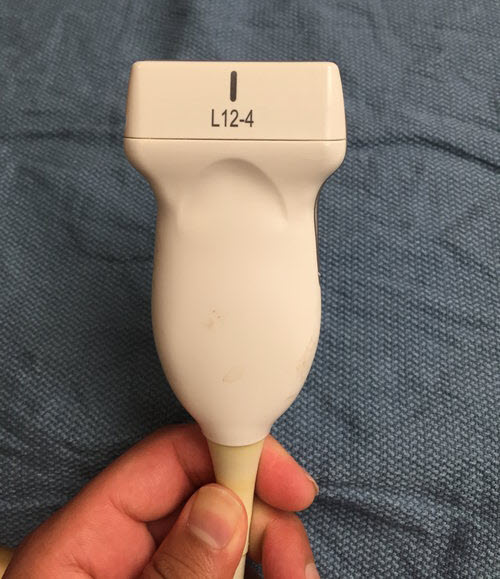
Linear array probe: High frequency probe (5-15MHz). Unlike the above probes, the array is parallel, allowing for high lateral resolution, as well as maintaining resolution with depth. Due to this, will only see structures directly below probe. Ideal for superficial soft tissue evaluation, evaluation of neurovascular structures, and procedural use.
Endocavitary Probe: Moderate frequency (8-15MHz). Curved array. Ideal for Intraoral or trans -vaginal use.
THE MODES
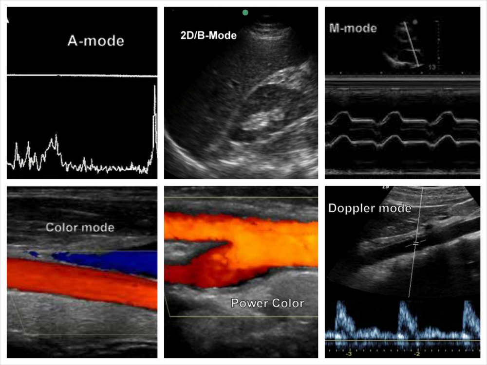
A-mode: Rarely used. Plots echo as function of depth where x-axis is depth and y-axis is amplitude. Primarily useful in ophthalmologic/retinal ultrasound and for use of ultrasound beam therapy
2D or B-mode: Standard scanning mode. Spatially oriented- Structures are seen as function of brighness (echoic vs anechoic), depth, and width. Provides a cross sectional view of underlying structures. Able to see structures in real time.
2D or B-mode: Standard scanning mode. Spatially oriented- Structures are seen as function of brighness (echoic vs anechoic), depth, and width. Provides a cross sectional view of underlying structures. Able to see structures in real time.
M-mode: takes a small section of horizontal beam (as would be seen in B-mode) and displays it over time. Useful to track motion/dynamic changes in a specific point of an image over a period of time. Vertical axis remains depth, while horizontal axis is time. (used in cardiac valve imaging and fetal heart rate measurements)

M-mode used to calculate TAPSE (tricuspid annular plane systolic excursion)
B-mode used as guidance for attempted vessel cannulation
Power Doppler: Similar to color doppler, but without assigning color to direction. Instead utilizes shades of color to represent level of flow. Useful for low flow states.
Color Doppler: Uses ‘doppler shift’, an induced change in frequency of returning echo to determine movement. Superimposes color to image to show flow either toward or away from probe, as indicated by a color key. By convention, movement towards probe is displayed red, and movement away as blue.
Color doppler used to show flow across mitral valve
Power doppler used to show low flow state in IVC/hepatic vein
Spectral doppler: Either via pulse-wave (alternating) or continuous (simultaneous transmission and reception). Allows for assessment of flow velocity at a specific point in the image which is then displayed as a function of time. Useful for echocardiography.

Spectral doppler used to quantify flow velocity across mitral valve
GETTING READY TO SCAN
ORIENTATION:
Scanning Planes: Ultrasound images are a 2-D representation of the underlying structure. Just as in other imaging modalities such as CT scanning or MRI, the image is displayed as a cross section in a particular plane. However, ultrasound can be more complicated in that the plane of section is determined by the sonographer. Just as one can obtain axial images, one can also obtain images in oblique planes.


Transverse plane- AKA axial plane. Perpendicular to the long axis of the body. Separates top from bottom.
Sagittal plane- Parallel to the long axis of the body, separating left from right. Midsagittal plane refers to the plane in the midline as opposed to parasagittal which is either left or right from midline.
Coronal plane- Parallel to long-axis of the body, perpendicular to sagittal plane. Separates anterior from posterior.
Oblique plane- Not at right angles to any of the above.
When an object or organ of interest does not lie in a standard plane, we often refer to it in terms of its axis.
Long Axis: the plane which extends parallel to the maximum length dimension of an object
Short Axis: the plane which is perpendicular to the long axis of an object
Probe indicator: There is always a dot, ridge or groove on one side of the probe which functions to assist with orientation. This allows one to determine which side of the probe corresponds to which side of the screen. By convention the indicator on the screen is a blue dot located on the top left of the screen image. By convention, the probe indicator has a specific position based on the imaging plane:
Transverse plane: Probe indicator towards the patient’s right side


Sagittal and Coronal planes: Probe indicator towards the patient’s head


HANDLING THE PROBES
It is important to have stable grasp on the probe, as the acquisition of a good image is often dependent on minute adjustments. In order to be able to make fine adjustments with the probe hand, it is best to hold the probe in the dominant hand with the thumb and index finger, using the other 3 fingers and ulnar aspect of the palm as a sort of ‘tripod’ to brace against the patient’s body.

MAKING ADJUSTMENTS:
Sweep: performed by sliding the entire probe in direction of its short axis over the surface of the body with a 90 degree angle of insonation-generally used to find a good imaging window
Sliding: performed by sliding the entire probe in direction of its long axis over the surface of the body with a 90 degree angle of insonation- generally used to find a good imaging window
Rock: similar to fanning, but in the left-right dimension (long axis) of the probe. Allows sonographer to extend imaging area to desired target not immediately below probe.
Fanning: performed by adjusting the angle of the probe body to the skin in anterior-posterior dimension (short axis) of the probe. This allows the ultrasonographer to scan through different planes of an organ from one imaging window.
Pressure/Compression: Pressure/Compressive Force on the probe into the body- used to manipulate vessels/tissues in areas of interest.
Rotation: performed by turning the probe on its long axis. This can allow the provider to obtain an image in an area with small imaging window (i.e ribs), or to obtain appropriate plane of section given variances in anatomy (i.e cardiac views).
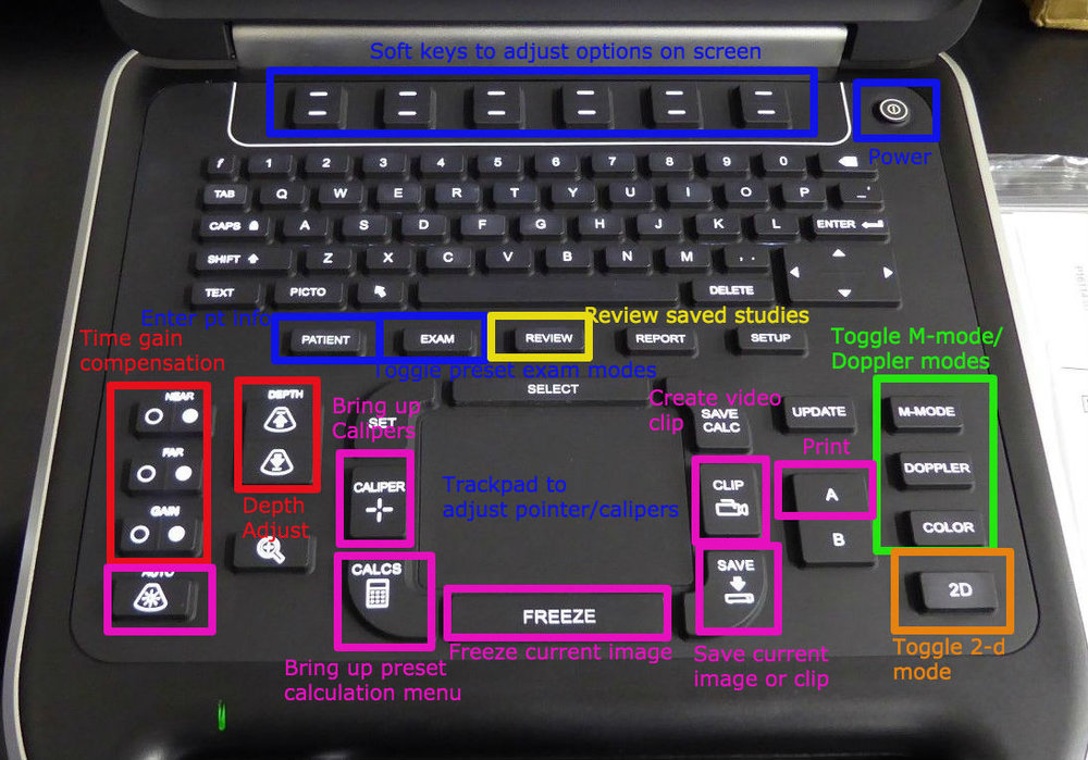
KNOBOLOGY DEFINITIONS
DEFINITIONS
Modes: Machines often preloaded with imaging modes for particular organs/indications which optimize settings for study of interest (e.g cardiac, vascular, abdominal, etc.)
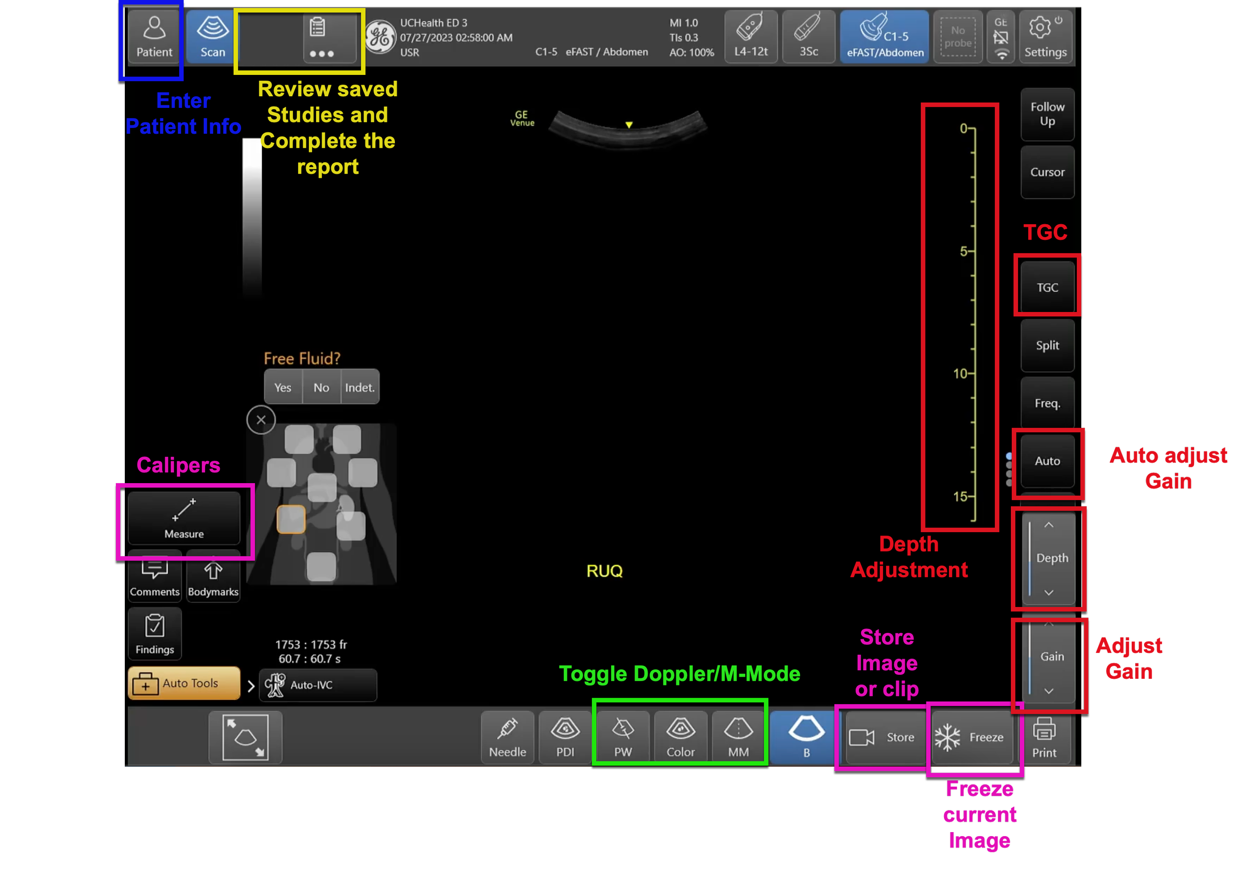
Depth: Adjust depth of field presented on screen
Focus: Improve resolution at a particular depth in image (not available on all machines)
Gain: Adjusts the strength of the signal returning to the probe- visualized on screen as contrast
Time gain compensation: Adjusts the gain for a specific depth in the image
AutoGain: allows the machine to calculate optimal gain settings
Calipers: used for measurement of distance
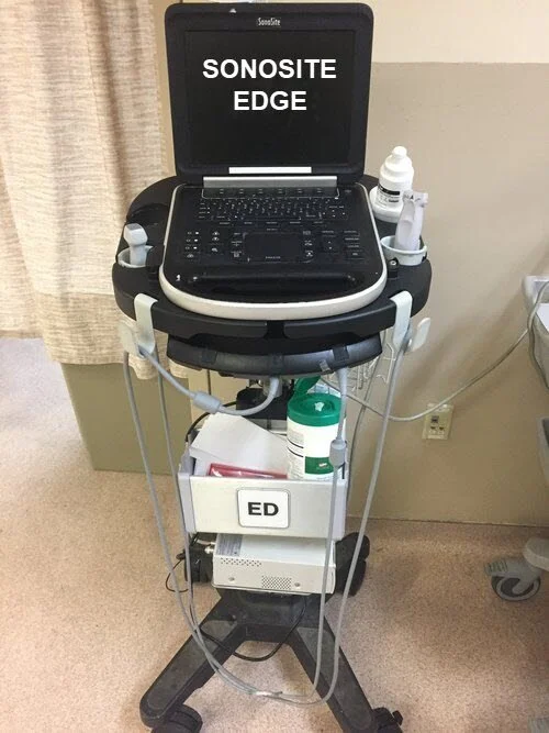
SONOSITE EDGE
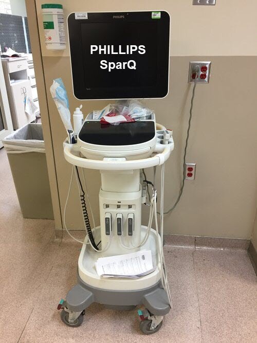
PHILIPS SPARQ

GE VENUE
Venue Worklist
Venue Qpathe Report
Venue Catheter to Vessel Ratio
Venue FAST Protocol
LUMIFY
Lumify Documentation Workflow
Lumify How To Guide
References
Bahner, D. P., Blickendorf, J. M., Bockbrader, M., Adkins, E., Vira, A., Boulger, C. and Panchal, A. R. (2016), Language of Transducer Manipulation. Journal of Ultrasound in Medicine, 35: 183–188. doi:10.7863/ultra.15.02036
Edelman, Sidney K. Understanding Ultrasound Physics. Woodlands, TX: ESP, 2012. Print.
Hoffman, Beatrice. "Ultrasound Physics." Ultrasound Physics. ACEP, n.d. Web.
Noble, Vicki E., and Bret Nelson. Manual of Emergency and Critical Care Ultrasound. Cambridge: Cambridge UP, 2011. Print.
Smith, Pattie. Bedside Ultrasound Guide for Emergency Medicine. Cincinnati, OH. Print